 86-0513-68903288
 13906298796@139.com

 русский
 Español
 عربى
Content
- 1 What a Blower CFM Number Actually Measures
- 2 Velocity Method: CFM Equals Velocity Times Area
- 3 Displacement Method for Positive Displacement Blowers
- 4 Reading CFM From a Blower Performance Curve
- 5 Converting Between SCFM and ACFM
- 6 Field Checks and Five Errors That Skew the Result
- 7 Frequently Asked Questions
A blower rated 600 CFM at the factory will often test near 540 CFM once the silencer, discharge pipe and diffuser are bolted on. That gap is not a manufacturing fault. It is the difference between the volume the rotors displace per revolution and the volume that actually crosses a measurement plane at the pressure and temperature existing there.
Three calculation routes cover almost every real case: a velocity traverse in the pipe, the displacement formula for positive displacement machines, and the manufacturer curve for centrifugal and turbo blowers. Each answers a slightly different question, and each can return a number that is wrong by twenty percent if the units or the measurement plane are handled carelessly.
What a Blower CFM Number Actually Measures
CFM is a volumetric flow rate: the cubic feet of gas passing a fixed plane in one minute, measured at the pressure and temperature at that plane. It is not a mass figure, so identical machines moving identical mass flows can report different CFM values on a cold morning and a hot afternoon.
The three labels on datasheets behave differently, and mixing them is the single most common source of sizing errors:
- ACFM reflects conditions at the measurement point, usually the blower inlet flange, at the moment of the reading.
- SCFM is corrected to a standard reference, typically 68 F, 14.7 psia and 36 percent relative humidity in US industrial practice, although 60 F reference points remain common in some sectors.
- ICFM is referenced to the blower inlet flange and is the figure most manufacturers quote when stating a machine capacity.
A three-lobe roots blower sized for wastewater aeration in a hot climate has to be calculated on mass flow of oxygen first, then converted back to the ACFM the machine will physically see. Skip that step and the basin runs short of air every August.
Velocity Method: CFM Equals Velocity Times Area
To calculate CFM in a duct or pipe, multiply the average air velocity in feet per minute by the cross-sectional area in square feet. For round pipe the area is 3.1416 times the radius squared.
The arithmetic is simple. The measurement is where accuracy is won or lost.
- Choose a measuring plane with seven to ten duct diameters of straight run upstream and at least three downstream. A plane just after an elbow can read far from average near the wall.
- Traverse the section. Log velocity at several points along two perpendicular diameters instead of one centreline reading; a 12 inch duct usually needs eight to twenty points for a defensible average.
- Average the readings, convert velocity to feet per minute if your instrument reports metres per second, then multiply by the area.
- Record gas temperature and barometric pressure at the same time. You need both for the standard-condition correction later.
A worked example makes the scale concrete. A 12 inch duct has a radius of 0.5 ft, so its area is 0.785 sq ft. An average velocity of 2,000 ft/min across that section gives about 1,570 CFM.
Instrument choice matters more than most guides admit. A pitot-static tube with a manometer works well above roughly 1,000 ft/min but drifts at low velocity. A thermal anemometer is better below that range. A calibrated flow nozzle or an installed vortex meter is the reference method when the number carries commercial consequences.
Displacement Method for Positive Displacement Blowers
For roots, rotary vane and screw blowers, delivered flow equals displacement per revolution multiplied by shaft speed, then reduced by slip losses.
Take a three-lobe roots blower displacing 0.55 cubic feet per revolution and running at 1,200 rpm. Theoretical displacement is 660 CFM. Slip back through the rotor clearances reduces that figure, and the reduction grows with discharge pressure.
| Discharge pressure (psig) | Volumetric efficiency | Delivered CFM |
| 0 | 95 percent | 627 |
| 4 | 92 percent | 607 |
| 8 | 89 percent | 587 |
| 12 | 85 percent | 561 |
The efficiency figures above are illustrative, not a catalogue guarantee. Real values depend on rotor clearance, bearing condition and the gas being handled. When the number has to hold up in a contract, request the shop performance test at your duty point; our roots blower specification guide lists the data worth asking for.
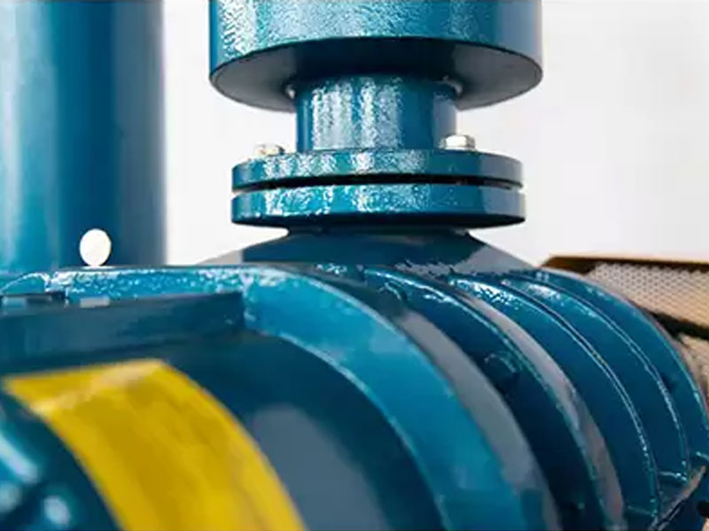 Wastewater Treatment Roots Blower for Aeration and Blower SelectionRoots-type positive displacement blower for wastewater aeration, with flow to 713.8 m³/min and pressure to 98 kPa; useful where duty-point performance must be verified.View Product →
Reading CFM From a Blower Performance Curve
On centrifugal, multistage and turbo blowers, flow is not fixed by speed alone. Delivered CFM is the point where the blower pressure-flow curve crosses the system resistance curve.
Manufacturers publish those curves at a stated inlet condition, a stated speed and a stated gas density. Move any of the three and the operating point moves with them. Three practical consequences follow:
- A dirty inlet filter raises system resistance, so the operating point slides along the curve and flow drops even though nothing inside the blower changed.
- Flow varies roughly with speed, pressure with the square of speed and shaft power with the cube. Cutting speed by ten percent drops flow by about ten percent but power by roughly twenty-seven percent.
- A curve drawn at 68 F inlet conditions overstates the pressure a machine can hold when the inlet gas arrives at 150 F, because density is lower.
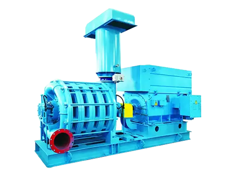 Medium Flow Inlet Multistage Centrifugal Blower for Water Treatment AerationMultistage centrifugal blower for water treatment aeration, with pressure rise up to 78 kPa, noise below 85 dB and options for coatings, materials and seals.View Product →
Converting Between SCFM and ACFM
Convert SCFM to ACFM by multiplying by the ratio of standard to actual absolute pressure and by the ratio of actual to standard absolute temperature, using degrees Rankine.
Example: a blower rated 500 SCFM at 68 F and 14.7 psia draws air at 90 F with a site barometric pressure of 14.4 psia. The correction is 500 x (14.7 / 14.4) x (550 / 528), which comes to about 531 ACFM. Mass flow is unchanged; the volume the machine handles at the inlet is not.
SCFM
- Reference condition, fixed
- Used to compare machines
- Basis for oxygen transfer and mass calculations
ACFM
- Site condition, variable
- Used for pipe sizing and velocity checks
- Basis for what the blower physically moves
| Unit | Value in CFM | 1 CFM in that unit |
| cubic metres per hour | 0.5886 | 1.699 |
| litres per second | 2.119 | 0.472 |
| cubic metres per minute | 35.31 | 0.0283 |
| litres per minute | 0.0353 | 28.32 |
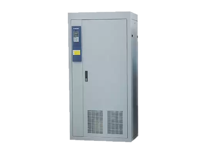 XBQ Frequency Conversion Starting Cabinet for Blower Speed ControlBlower starting cabinet with three-phase 380V input, 0–400 Hz output and IP20 protection; supports speed regulation for energy savings.View Product →
Because flow tracks speed almost linearly, a variable frequency drive is often the cheapest way to trim an oversized blower down to the CFM the process actually needs, and the saving in shaft power is larger than the saving in flow.
Field Checks and Five Errors That Skew the Result
Most CFM disputes come down to the measurement plane, mixed units or ignored slip rather than a defective machine.
- A single centreline velocity reading. In developed flow it overstates average velocity by five to fifteen percent, and downstream of a valve it can be far worse.
- Comparing an SCFM quotation with an ACFM field measurement. On a hot day the two numbers differ by more than ten percent before anything is actually wrong.
- Treating nameplate displacement as delivered flow. Rotor clearance, wear and rising pressure all take a cut.
- Measuring close to a silencer, expansion joint or bend, where the velocity profile has no chance to settle.
- Ignoring altitude. At 1,500 m a fixed-displacement blower moves nearly the same ACFM but roughly fifteen percent less mass, and the pressure it can build falls accordingly.
Buyers can shortcut most of this by requesting factory test data at the site inlet condition. The engineering behind those tests sits in the company manufacturing and quality overview, which covers the rotor machining and balancing steps that decide how close delivered flow sits to the published curve.
Frequently Asked Questions
Can I calculate blower CFM from motor amps?
Only as a rough check. Current tracks shaft power, and shaft power depends on flow and pressure together, so the same amps can mean high flow at low pressure or low flow at high pressure. Without a calibrated power curve at a known discharge pressure, amps alone will not give you CFM.
Does a larger blower always deliver more CFM?
No. Delivered flow depends on the system resistance the machine works against. A larger blower throttled by undersized pipe or a partly closed valve can move less air than a smaller unit on an open system.
How accurate is the velocity traverse method?
With a proper multi-point traverse in a good measuring plane it is typically within three to five percent. A single-point reading can easily be ten to twenty percent out, which is enough to make a correctly sized blower look like a failure.
Why does my blower CFM drop as pressure rises?
On a positive displacement machine, higher discharge pressure pushes more gas back through the rotor clearances, so slip increases and delivered flow falls. On a centrifugal machine, the operating point simply slides along the curve toward lower flow.