русский
 Español
 عربى
عربىContent
- 1 The Core Mechanism: How Rotation Produces Airflow
- 2 Direct Drive: Simplicity and Mechanical Efficiency
- 3 Belt Drive: Flexible Speed Adjustment Without Electronics
- 4 Variable Frequency Drive (VFD): Precision Control Over Rotational Speed
- 5 Gear Drive and High-Speed Direct Coupling
- 6 Comparing Drive Methods Side by Side
- 7 Starting Methods and Their Effect on Drive Life
- 8 Air Suspension and Magnetic Bearing Blowers: No Mechanical Drive Contact
- 9 Matching Drive Method to Your Operating Profile
A centrifugal blower moves air by converting rotational kinetic energy into pressure — but the quality of that rotation depends entirely on how the impeller is driven. In our experience manufacturing industrial blowers for wastewater treatment, chemical processing, and pneumatic conveying applications, the drive method is one of the most consequential decisions buyers overlook. Get it right, and you gain efficiency, longevity, and low maintenance costs. Get it wrong, and you face vibration issues, energy waste, and premature failure.
This article explains the main ways a centrifugal blower is turned, the mechanical principles behind each approach, and how to match the right drive method to your operating conditions.
The Core Mechanism: How Rotation Produces Airflow
Before discussing drive methods, it helps to understand what happens when the impeller spins. In a centrifugal blower, the rotating impeller draws air in axially through the inlet and accelerates it radially outward using centrifugal force. The air then enters a volute or diffuser casing where velocity is converted into static pressure.
The impeller speed directly governs pressure output and airflow volume. A small change in rotational speed produces a disproportionately large change in performance — following the fan affinity laws: airflow is proportional to speed, pressure is proportional to the square of speed, and power is proportional to the cube of speed. This is why the method used to turn the blower — and how precisely that speed can be controlled — matters so much in real applications.
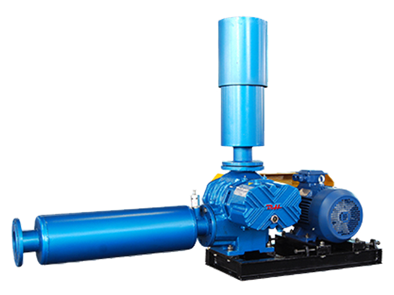
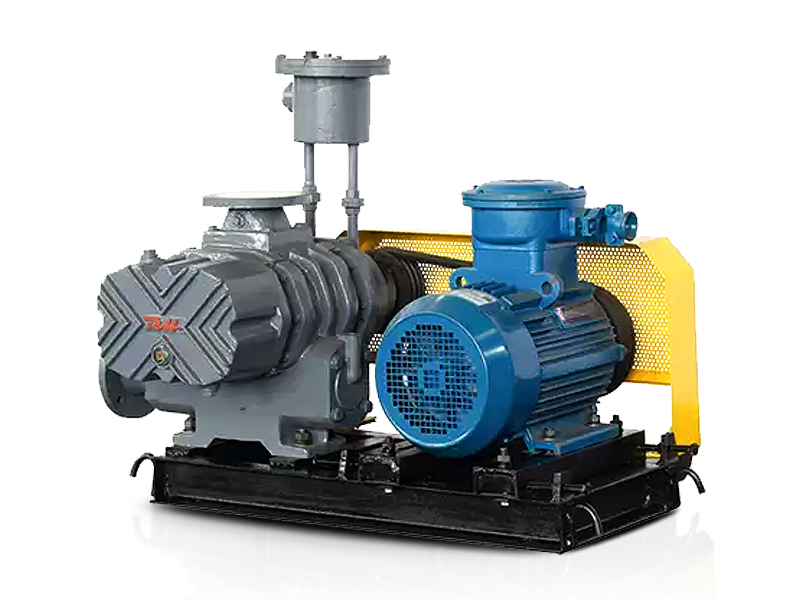
Direct Drive: Simplicity and Mechanical Efficiency
In a direct-drive configuration, the impeller is mounted directly onto the motor shaft with no intermediate components. The motor shaft and the blower shaft are either the same component or are coupled rigidly using a flexible disc or jaw coupling.
Advantages of Direct Drive
- No transmission losses from belts or gears — mechanical efficiency typically exceeds 98%
- Fewer wear components, which reduces scheduled maintenance intervals
- Compact footprint — the motor and blower occupy a shared axial envelope
- No belt slip or tension misalignment to introduce vibration
Limitations to Consider
Direct drive locks the blower to the motor's rated speed — typically 2,900 RPM on a 2-pole motor at 50 Hz, or 3,500 RPM at 60 Hz. This is fine for fixed-speed applications, but it eliminates flexibility when your process requires variable airflow. Additionally, any motor fault transmits directly to the impeller shaft, so coupling selection and alignment precision are critical.
Direct drive is most suitable for clean air applications, stable load profiles, and installations where maintenance access is limited.
Belt Drive: Flexible Speed Adjustment Without Electronics
In a belt-drive arrangement, the motor drives a pulley on its shaft, which transmits rotation to a second pulley on the blower shaft via a V-belt or poly-V belt. By selecting different pulley diameter ratios, you can change the blower speed independently of motor speed.
For example, if a motor turns at 1,450 RPM and you need the blower to run at 2,175 RPM, a pulley ratio of 1:1.5 achieves this without any electronics. This makes belt drive a practical and low-cost way to fine-tune output during initial commissioning.
Where Belt Drive Excels
- Speed adjustment without changing the motor or adding a VFD
- Belt slippage acts as a soft mechanical overload protection
- Lower initial cost compared to VFD-equipped direct drive systems
- Easy field adjustment by swapping pulleys
Where Belt Drive Falls Short
Belt transmission efficiency is typically 93–96%, compared to over 98% for direct drive — a gap that compounds at high operating hours. Belts also stretch over time, requiring periodic tensioning. In dusty or humid environments, belt wear accelerates significantly, and loose belts introduce vibration that stresses bearings. For continuous 24/7 industrial operations, belt replacement cycles of 4,000–8,000 hours are common.
Variable Frequency Drive (VFD): Precision Control Over Rotational Speed
A Variable Frequency Drive (VFD) controls blower speed by adjusting the frequency of AC power delivered to the motor. Since AC motor speed is directly proportional to supply frequency, a VFD can smoothly vary the blower's RPM across a wide range — typically 20% to 100% of rated speed — without any mechanical changes.
This is the most energy-efficient method of speed control in applications with variable demand. Because power consumption scales with the cube of speed, reducing blower speed by just 20% cuts energy use by roughly 49%. In a wastewater aeration system running 8,760 hours per year, this translates to substantial operating cost savings.
Typical Applications for VFD-Controlled Centrifugal Blowers
- Sewage treatment aeration tanks where oxygen demand fluctuates by time of day
- Pneumatic conveying systems with variable material loads
- Industrial drying processes where airflow must track temperature setpoints
- Chemical fermentation where dissolved oxygen control is critical
VFDs also enable soft-start capability, gradually ramping the motor from 0 to operating speed. This eliminates the large inrush current spike (typically 6–8× full-load current) that occurs with across-the-line starting, which extends motor and bearing life significantly in high-cycle applications.
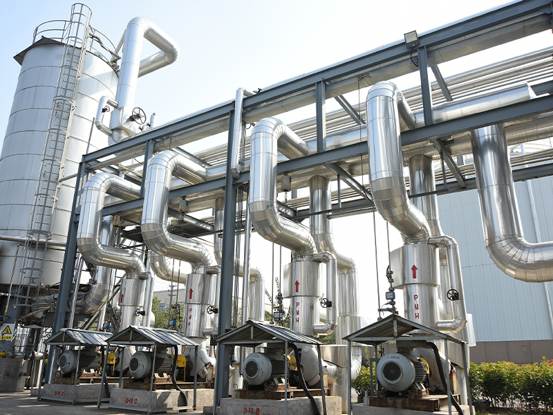
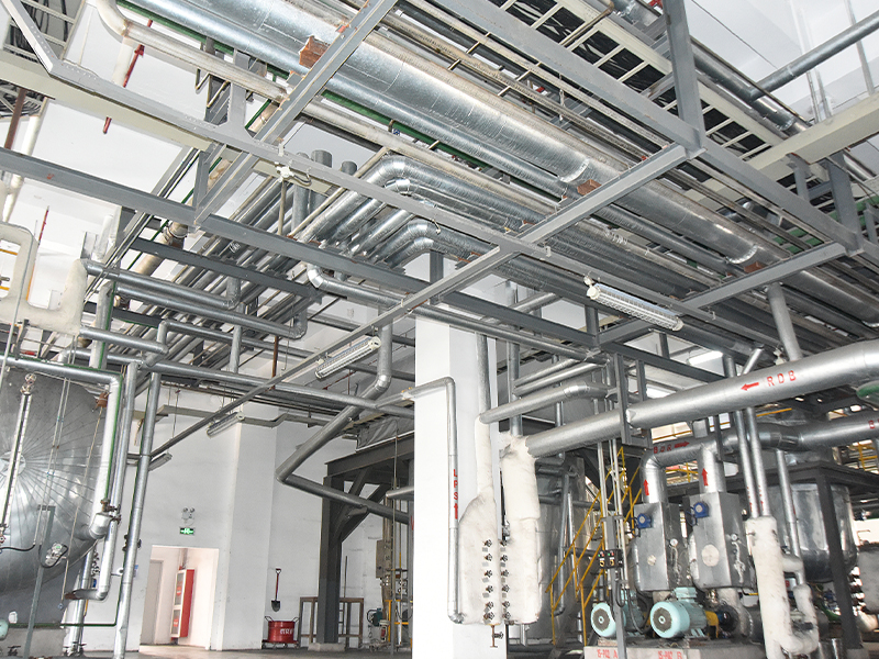
Gear Drive and High-Speed Direct Coupling
Some centrifugal blower designs — particularly multistage units — require impeller speeds that standard AC motors cannot achieve directly. In these cases, a step-up gearbox or high-speed coupling is used to increase shaft speed before it reaches the impeller.
Gear-driven blowers can operate impellers at 10,000–40,000 RPM or higher, enabling the compact, high-pressure designs used in biogas compression, instrument air supply, and industrial gas handling. The tradeoff is increased mechanical complexity, oil lubrication requirements for the gearbox, and higher acoustic output from gear mesh noise.
Our multistage centrifugal blower product line represents an engineered solution for applications that need sustained high-pressure output with efficient multi-stage compression — a category where impeller speed and drive design are closely co-engineered.
Comparing Drive Methods Side by Side
The table below summarizes the key characteristics of each drive method to help with selection:
| Drive Method | Transmission Efficiency | Speed Control | Maintenance Demand | Best Fit |
|---|---|---|---|---|
| Direct Drive | ~98–99% | Fixed (motor speed) | Low | Stable, fixed-load applications |
| Belt Drive | 93–96% | Adjustable via pulleys | Moderate (belt wear) | Low-budget, light-duty installations |
| VFD + Direct Drive | ~96–98% (VFD loss included) | Continuous, precise | Low | Variable-demand, energy-sensitive processes |
| Gear / High-Speed Drive | 94–97% | Fixed ratio (can add VFD) | High (lubrication, gear wear) | High-pressure multistage applications |
Starting Methods and Their Effect on Drive Life
How a centrifugal blower is started is as important as how it is continuously turned. The three most common starting methods each place different demands on the drive system:
- Direct-on-line (DOL) starting — The motor is connected directly to full supply voltage. Simple and low cost, but generates an inrush current spike of 6–8× rated current and a corresponding mechanical shock through the coupling and shaft. Suitable only for small motors below ~7.5 kW in most grid-connected applications.
- Star-delta starting — The motor starts in star configuration (reduced voltage), then switches to delta at approximately 80% speed. This reduces starting current to roughly one-third of DOL. Widely used for blowers in the 15–75 kW range where VFDs are not economically justified.
- Soft starter or VFD ramp-up — Electronically controlled ramp from zero speed to operating speed over a set time (typically 5–30 seconds). Produces the gentlest mechanical stress and is the preferred method for high-cycle applications or where impeller inertia is large.
In applications where blowers start and stop multiple times per day — such as intermittent aeration in biological wastewater treatment — VFD soft-start can extend bearing and coupling service life by 30–50% compared to DOL starting, based on fatigue cycle analysis from field maintenance records.
Air Suspension and Magnetic Bearing Blowers: No Mechanical Drive Contact
A newer category worth understanding is the air suspension or magnetic bearing blower, where the impeller shaft is levitated by an air or magnetic bearing system — meaning there is no physical contact between rotating and stationary components during operation. These units are driven by a high-frequency permanent magnet motor integrated directly with the impeller shaft, operating at speeds typically between 20,000 and 50,000 RPM.
Because there is no mechanical friction in the bearing system, these blowers consume 15–25% less energy than equivalent-output traditional centrifugal or roots-type blowers in aeration-duty cycles. They also require no oil lubrication, dramatically simplifying maintenance. We offer an air suspension blower product line for buyers who prioritize energy efficiency and long service intervals in continuous-duty applications.
Matching Drive Method to Your Operating Profile
Based on our production and application experience, here is a practical framework for matching drive method to your specific situation:
- Fixed demand, clean environment, limited budget: Direct drive with DOL or star-delta starting. Focus on motor quality and precision shaft alignment.
- Variable demand, energy costs are significant: Direct drive plus VFD. The payback period for VFD addition is typically 12–24 months in continuous-duty industrial settings.
- High pressure required (above 50 kPa), moderate flow: Consider multistage centrifugal or gear-driven designs with appropriate starting protection.
- Continuous 24/7 duty, high start-stop frequency, or strict energy targets: Air suspension blowers with integrated high-speed drives are the optimal solution.
- Hazardous or explosive atmosphere: The motor and drive enclosure must meet ATEX or equivalent ratings; belt drive can offer an additional layer of mechanical isolation in some configurations.
If you are evaluating centrifugal blower options for your project, our industrial blower product range covers multiple drive configurations designed for demanding industrial environments. We are happy to advise on the most suitable drive arrangement for your specific flow, pressure, and duty-cycle requirements.